Prototype
i had this Longer Ray5 Laser-Engraver and i always wondered how to convert it to a plotter...
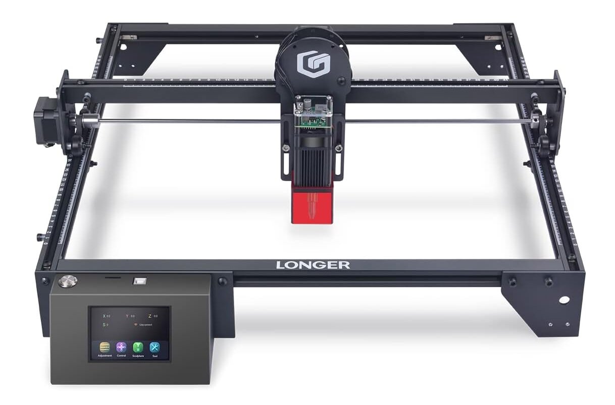 |
>>> |  |
| engraver | plotter |
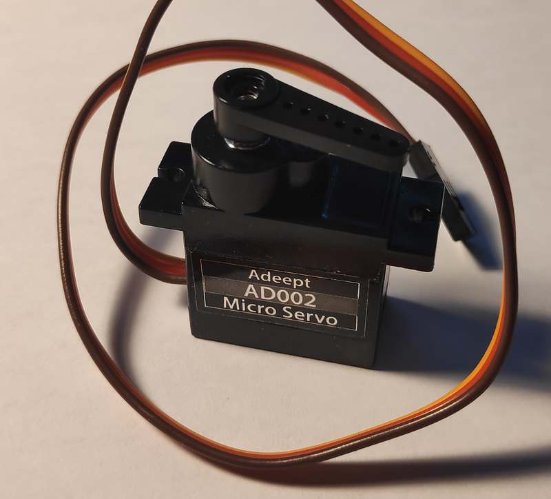
using a standard servo:
...turned out that electronically there was not much conversion necessary because:
The Engraver is driven by a Makerbase board (ESP32 chip).
The laser is cntrolled by 5000 to 20000 Hz PWM signal.
in an undocumented setting ($33) the board can be configured to much lower PWM frequency (can either be done in webinterface or telnet connetion or serial or directly in the gcode-file)
$33=50
and 50Hz is the PWM frequency of standard servos, so i gave that a try...
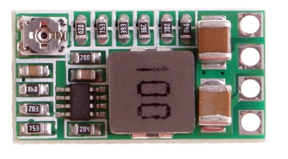
however the laser is driven by 12 V and the servo only 5V, so iadded some DC-DC step down buck converter (voltage needs to be adjusted at the small potentiometer):
added some small board and connectors the white one is the laser-connector (12V,GND,PWM) and the black one goes to the servo (GND,5V,PWM):
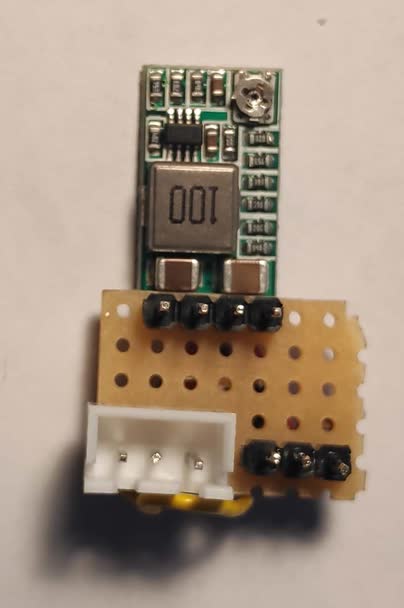
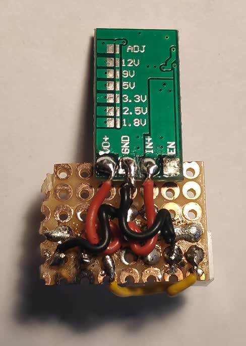
its small enough to let it hang loose on the cables (for now).
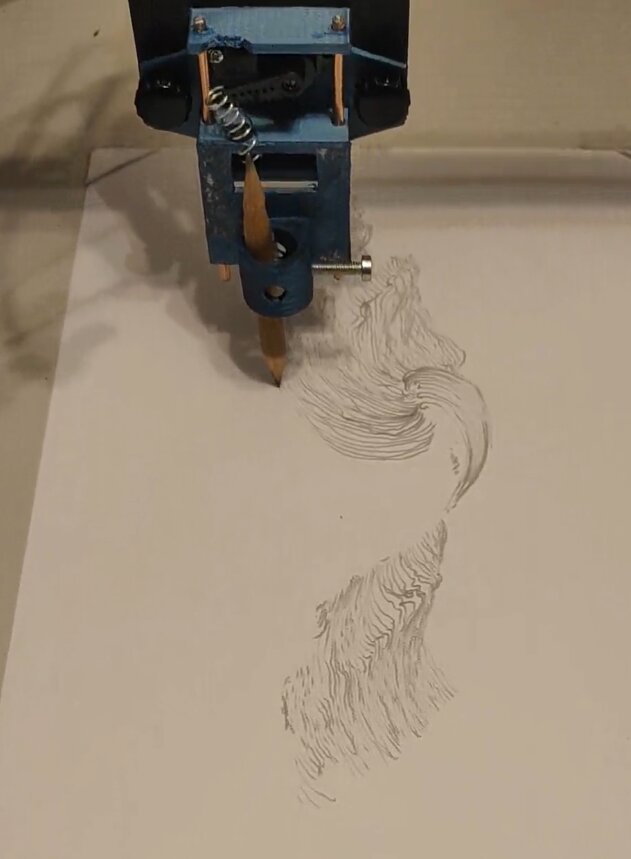
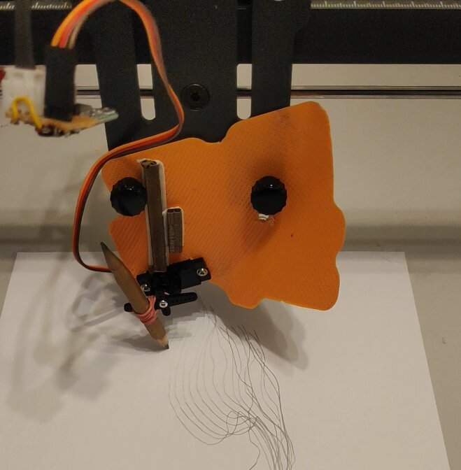
and it worked... here a 1st test with a wildly mounted servo (bc i was impatient):
the servo is then driven by spindle-speed commands in G-Code (e.g. "G1 X100 Y100 S110")
info about servo:
the pwm of servo uses up to ~2200us (varies with different vendors) pulse-width (about 1/10th from full 20ms PWM cycle), so if our max spindlespeed is 1000 (preset of longer-raw5 which is 100% of PWM cycle) then only spindlespeed values up to ~110 should be used, because the servo might not be able to cope. ...i tested it and above 125 (and below ~30) the servo actually behaved weirdly and turned around all over or slowly drifted - which makes sense.
so to be safe S-values should ideally be somewhere between lets say 50 an 110 (might be different for other servos)
turned out for my servo mount the proper values were 100 just touching paper and the continuously higher pressure up until 115.
...as a followup i did some more exact calculations here:
SERVO:
servo PWM frequency 50Hz -> period = 20000 us
servo pulse widths: 500..2500 us -> 0..180 deg

Engraver RPM values (assuming 8 bit res - so ~0.4% clamped off on both ends -> 0.4%..99.6%):
r0 0    =  0.4 % duty cycle =    80 us (t0)
r1 1000 = 99.6 % duty cycle = 19920 us (t1)

values: 0..1000 -> 0.4 .. 99.6 % of 20000 -> 80us..19920us

RPM-val = r0+(t-t0)/(t1-t0)*(r1-r0)

RPM-val for   0 deg ->  500us = 0.025 * 20000 us =  (500-80)/(19920-80)*1000 =  21.17
RPM-val for 180 deg -> 2500us = 0.125 * 20000 us = (2500-80)/(19920-80)*1000 = 121.98

...so RPM-values should vary from 22 to 122 for 0..180 degree
Pen Holder
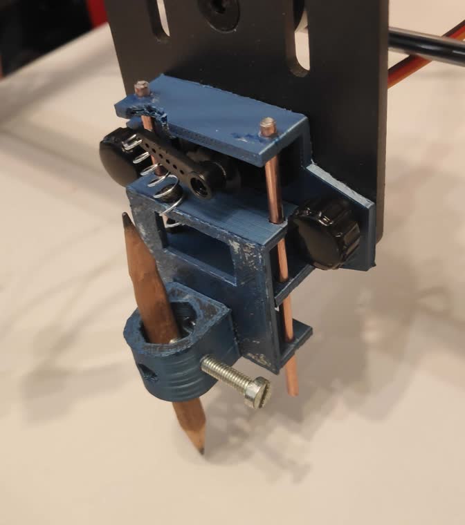
Finally i modelled and 3d-printed some pen holder to make proper plots.
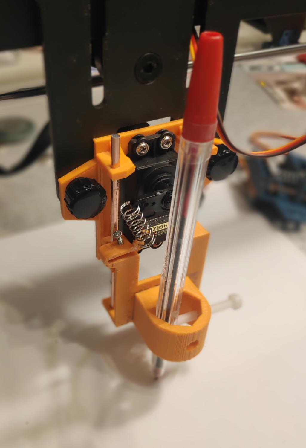
this pen holder has the servo connected to the pen sledge by a spring, so i can control pen-pressure continuously (...my 3d-printer is not the best of its type ;-P):
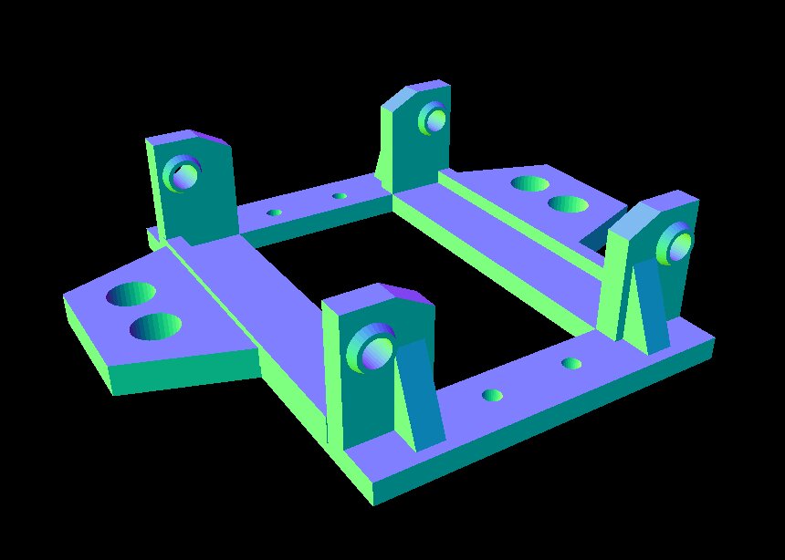
here my 2 obj files ready for 3d-printing - click image for link to obj-file (save link as...):
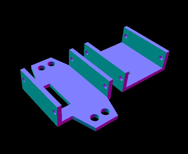

there's no mounting hole for the actual pen-part - i just drilled that by hand. and the spring mount was also quite improvised, just bolted it on bottom of the lower sledge and wound it through one of servo holes.
the 2 parts of the pen-sledge should be connected by two 8cm long 3mm bolts (glued on one side).
in principle one could also skip the spring and use a standard servo-saver for varying the pen-force (but i had none at hand...).
edit: ...new improved versions here for download (can also hold bigger 40mm servos):


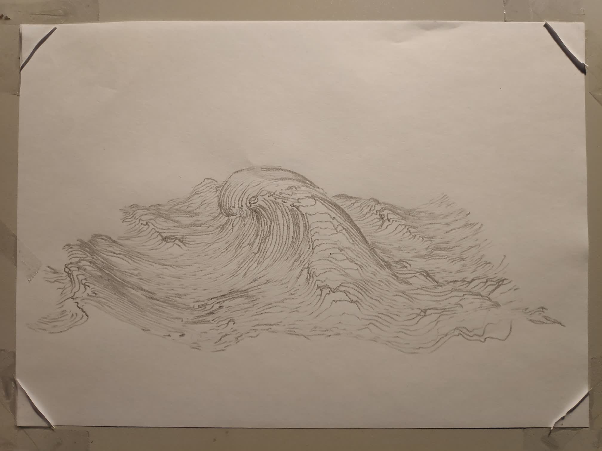
Results
in action...
final plot...